Lights - Add An On/Off Switch

    Lights - Add An On/Off Switch

    Lights - Add An On/Off Switch

    Published by
    Designer Media Ltd


    How to Create your Fan Light Switch


       Information
    This tutorial will show you how to add a switch to turn off those bright LED fan lights they use.

       Warning
    This project involves soldering and bare wire leads. Always take the appropriate cautions when working with electrical parts.

    While it may seem very daunting at first, this tutorial is actually extremely simple once you see what to do.


    Items needed:
    • Computer fan
    • 22 Gauge Wire
    • 4 pin FEMALE (and male if you want) MOLEX connectors (to connect to PSU)
    • Wire clippers
    • Heat Shrink (optional, but highly recommended)
    • Solder and Soldering Iron (or pliers and cable connectors if you don't mind it)
      • *This tutorial will assume that you know how to solder, and that is the method you will use. If you have any questions about soldering or using connectors, feel free to ask*


    Set up:
    Set up your Soldering station to your preference, and make sure you have wire (and connectors) and solder. I used 22 Gauge wire because it is about the same size as the wire used in the fan already. I also recommend you use a Test PSU to test this mod until you are sure it works.
       Warning
    When you touch two leads from the power supply (i.e. The yellow and red wires, or the yellow and black, etc) you will short out the power supply. If this occurs, immediately unplug the PSU and take the wires apart. This is why I recommend heat shrink.


    Step 1:
    Remove the plastic sticker covering the back of the fan. This will be the side with the wires leading to it, generally the one with the voltage information on it (just the one you SHOULDN'T remove...)

    Step 2:
    Locate each of the fan LED wires. My fan was cool enough to have the + and - symbols located on the circuit board, so it was easy to figure out which was which.
    You will need to desolder the NEGATIVE wire from the circuit board (all of them)
       Warning
    If you solder the positive side, and then attach them directly to the PSU, you WILL blow out your LEDs, rendering them so much junk


    Step 3:
    This is the hardest step. You need to take a small wire, and solder it to each LED wire. It would look better if you could run the wire under the plastic to keep it down, but this was EXTREMELY difficult to do, so I lift some of it over the plastic. How much you want to struggle with that is your decision, but the step remains the same.

    Step 4:
    Now you have an extra fan wire that needs to be grounded for the lights to work. It needs to be attached to a black PSU wire (the middle 2 connectors on the 4 pin molex).
    This can be accomplished by merely adding a switch in the line, then sending it out to a molex pin with the fan plug.
    I know this step may sound very confusing right now, but I have yet to actually do this part. When I do, I will add pictures and more detail to clear it up.

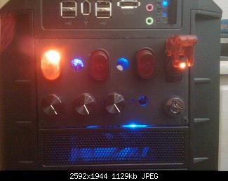
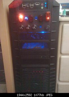
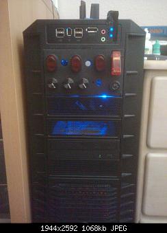
    Here is my semi-completed project. I have utilized all 5 sections of this series. To the right is my keyed start switch (the key switch at bottom right and aircraft safety toggle switch). On the top is my cathode switch and my soon-to-be fan light switches. The bottom has 3 of my 4 potentiometer speed controllers.
    Lights - Add An On/Off Switch-finished-close.jpg
    Lights - Add An On/Off Switch-finished-lit.jpg
    Lights - Add An On/Off Switch-finished-dark.jpg


    Hope this helps out the modders!

    ~Lordbob


    Related Tutorials

    Computer Mod Series:
    1. PSU - Jump Start
    2. Start Button - Customize
    3. Fans - Speed Controller
    4. Lights - Add An On/Off Switch


  1. Posts : 2,737
    Windows 7 Enterprise (x64); Windows Server 2008 R2 (x64)
       #1

    Some pictures of your fan mod would be extremely nice. :)
      My Computer


  2. Posts : 6,885
    Windows 7 Ultimate x64, Mint 9
    Thread Starter
       #2

    WindowsStar said:
    Some pictures of your fan mod would be extremely nice. :)
    Yes, it would.
    I only took one, but I will add it in soon.

    When I fix up my second LED fan, I will take many more.

    ~Lordbob
      My Computer


  3. Posts : 2,737
    Windows 7 Enterprise (x64); Windows Server 2008 R2 (x64)
       #3

    Looking like the cockpit of a 767 ... hehehe
    Attached Thumbnails Attached Thumbnails Lights - Add An On/Off Switch-boeing_767_cockpit.jpg  
      My Computer


  4. Posts : 6,885
    Windows 7 Ultimate x64, Mint 9
    Thread Starter
       #4

    WindowsStar said:
    Looking like the cockpit of a 767 ... hehehe
    Naw, more like a space station!

    Nemix77 said:
    Wow! I love the space station PC look and launch missiles button.
    ~Lordbob
      My Computer


  5. Posts : 1,223
    Win 10 x64 Pro x64 / Ubuntu 15.10 x64
       #5

    Hey LordBob, I just thought of something that might improve this process a bit... I'm not sure of the correct name, so trying to Google a picture for it is a bit tricky, but you know the plugs used to connect the power / HDD access lights to the motherboard? What about plugging the LED straight into that and doing the solder work on the cables from the plug instead?

    I'm sure the LED pins would fit quite nicely in one of those plugs, and if so, that would make the process of connecting an LED much easier.
      My Computer


  6. Posts : 6,885
    Windows 7 Ultimate x64, Mint 9
    Thread Starter
       #6

    ZaLiTH said:
    Hey LordBob, I just thought of something that might improve this process a bit... I'm not sure of the correct name, so trying to Google a picture for it is a bit tricky, but you know the plugs used to connect the power / HDD access lights to the motherboard? What about plugging the LED straight into that and doing the solder work on the cables from the plug instead?

    I'm sure the LED pins would fit quite nicely in one of those plugs, and if so, that would make the process of connecting an LED much easier.
    You can just use the 3 pin fan connectors (male) to connect to the case lights, but plugging into the mobo would need the right kind. Easiest thing to do would be to find an old case and unplug those

    I wish I had thought of this sooner. Would have saved my case connectors.

    ~Lordbob
      My Computer


  7. Posts : 1,223
    Win 10 x64 Pro x64 / Ubuntu 15.10 x64
       #7

    Lordbob75 said:
    You can just use the 3 pin fan connectors (male) to connect to the case lights, but plugging into the mobo would need the right kind. Easiest thing to do would be to find an old case and unplug those

    I wish I had thought of this sooner. Would have saved my case connectors.

    ~Lordbob
    Sorry, I wasn't referring to actually connecting the lights directly to the motherboard... Simply using those same plugs to plug the LED into, as opposed to soldering the wires onto the LED connectors.
      My Computer


  8. Posts : 6,885
    Windows 7 Ultimate x64, Mint 9
    Thread Starter
       #8

    ZaLiTH said:
    Lordbob75 said:
    You can just use the 3 pin fan connectors (male) to connect to the case lights, but plugging into the mobo would need the right kind. Easiest thing to do would be to find an old case and unplug those

    I wish I had thought of this sooner. Would have saved my case connectors.

    ~Lordbob
    Sorry, I wasn't referring to actually connecting the lights directly to the motherboard... Simply using those same plugs to plug the LED into, as opposed to soldering the wires onto the LED connectors.
    That would work as well.

    ~Lordbob
      My Computer


  Related Discussions
Our Sites
Site Links
About Us
Windows 7 Forums is an independent web site and has not been authorized, sponsored, or otherwise approved by Microsoft Corporation. "Windows 7" and related materials are trademarks of Microsoft Corp.

© Designer Media Ltd
All times are GMT -5. The time now is 22:38.
Find Us